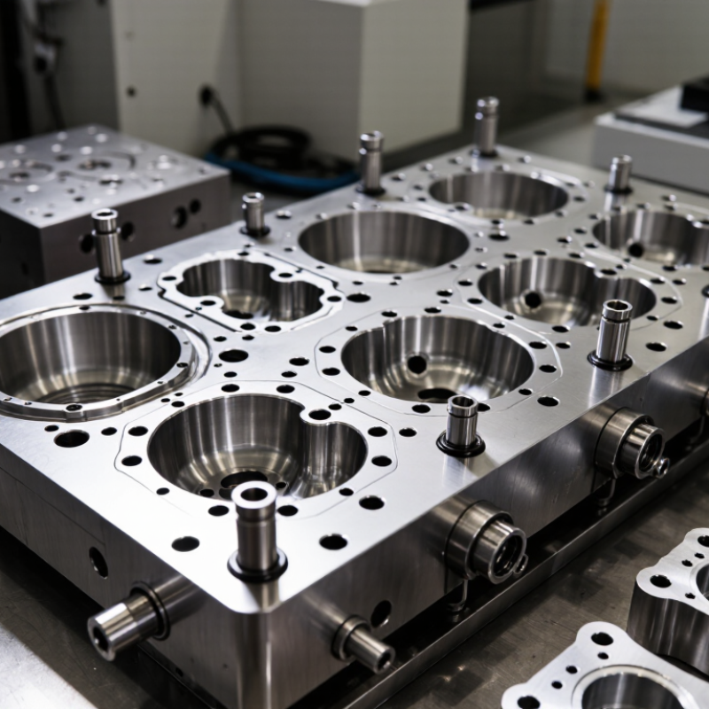
| 1 | Mold Steel Grade | Check the hot-work tool steel grade, hardness, toughness, heat resistance, and documented heat-treatment process. | A commonly used hot-work steel may be heat-treated to approximately 44–52 HRC, depending on the design and application. | Verify hardness records and inspect for soft spots, chipping, and heat checking during scheduled inspections. | Appropriate steel selection can reduce premature cracking, soldering, and erosion under repeated thermal cycling. |
| 2 | Thermal Fatigue Resistance | Evaluate the mold’s resistance to heat checking caused by repeated heating and cooling at the cavity surface. | High thermal gradients and rapid temperature changes are major contributors to surface cracking; preheating and controlled cooling are essential. | Monitor heat-check depth, polish early cracks where appropriate, and review process temperatures if cracking accelerates. | Better thermal-fatigue resistance generally extends cavity service intervals and delays major rework. |
| 3 | Cooling System Design | Review cooling-channel location, diameter, flow balance, accessibility, and separation from the cavity surface. | Cooling should be sufficiently uniform to limit hot spots; channel layouts must be validated for the part geometry rather than selected by a fixed universal spacing. | Use filtered coolant, check flow regularly, and remove scale or blockage before cooling performance declines. | Uniform cooling reduces thermal stress, distortion, soldering, and localized die wear. |
| 4 | Cavity and Core Surface Finish | Inspect polishing quality, machining marks, sharp transitions, radii, and areas likely to trap aluminum. | Surface finish should match the required part appearance and release performance; sharp internal corners should be avoided where the design permits. | Clean and polish affected areas using controlled procedures; avoid removing excessive material from critical parting surfaces. | Smooth, properly radiused surfaces reduce sticking, erosion, stress concentration, and repair frequency. |
| 5 | Ejector and Slide Design | Check ejector-pin balance, guide support, return mechanisms, slides, lifters, and clearances at operating temperature. | Ejection forces should be distributed across suitable areas of the casting; unsupported or overloaded pins are common wear and fracture risks. | Lubricate approved moving components, inspect for galling, and measure abnormal clearance or uneven pin movement. | Balanced ejection reduces pin breakage, cavity damage, casting distortion, and unplanned downtime. |
| 6 | Venting and Vacuum Capability | Evaluate vent locations, vent depth, overflow design, vacuum compatibility, and the risk of trapped gas or flash. | Vents must be effective without creating excessive flash; vent dimensions depend on alloy, fill speed, part geometry, and process conditions. | Clean vents and overflows frequently because aluminum residue and oxides can reduce gas evacuation. | Effective venting limits gas-related defects, burn marks, erosion, and cleaning-related damage to the parting line. |
| 7 | Parting Line and Flash Control | Review parting-line alignment, shut-off strength, locating features, locking support, and the expected flash zone. | Parting surfaces should remain flat and properly supported; excessive flash often indicates wear, misalignment, insufficient locking, or process overload. | Measure parting-line mismatch, remove flash carefully, and correct alignment problems before they damage shut-offs. | Strong shut-offs and accurate alignment preserve sealing surfaces and reduce repeated welding or re-machining. |
| 8 | Surface Treatment and Protection | Determine whether nitriding, coating, or another surface treatment is suitable for high-wear, soldering, or erosion-prone areas. | Treatment selection should be based on alloy chemistry, die temperature, lubrication, filling speed, and the specific failure mode—not on hardness alone. | Follow the treatment supplier’s cleaning and repair limits; damaged treated surfaces may require controlled rework or re-treatment. | A suitable treatment can improve resistance to soldering, erosion, and adhesive wear in targeted areas. |
| 9 | Repairability and Spare Components | Confirm whether inserts, slides, pins, cores, wear plates, and cooling components can be replaced without rebuilding the entire mold. | Modular inserts and standardized replaceable components usually shorten repair time and reduce the cost of restoring critical dimensions. | Keep dimensional records, spare wear components, inspection gauges, and documented repair limits. | Repairable construction can substantially extend usable service life even when selected components reach their wear limit. |
| 10 | Service-Life Validation | Request a preventive-maintenance plan, inspection criteria, trial-run data, dimensional capability results, and a clearly defined life estimate. | Mold life varies widely with alloy, casting size, cycle time, thermal control, lubrication, shot velocity, maintenance quality, and acceptance criteria; avoid unsupported fixed-shot guarantees. | Track cycles, repairs, cooling flow, cavity dimensions, flash, soldering, and heat checking in a maintenance log. | Data-based monitoring helps predict wear and replace components before quality or safety is affected. |